Useful tools and tables to do calculations and conversions for roof and wall cladding. Just choose the correct online caculator, input your values, and get the answer.
COP v25.03:Useful-Information;
18.1A Measurement Conversions
| To convert from this | into this To convert this back | multiply by this divide by this |
|---|---|---|
| atmosphere | millibar | 1013.25 |
| atmosphere | pascal | 101.325 |
| cubic foot | cubic metre | 0.028317 |
| cubic inch | cubic millimetre | 16387.1 |
| cubic yard | cubic metre | 0.764555 |
| foot | metre | 0.3048 |
| foot per minute | metre per minute | 0.3048 |
| foot per minute | metre per second | 0.00508 |
| foot per second | metre per second | 0.3048 |
| foot pound force per second | watt | 1.35582 |
| gallon (Imp) | litre | 4.54609 |
| gallon (US) | litre | 3.78541 |
| inch | metre | 0.0254 |
| inch | millimetre | 25.4 |
| inch mercury | kilopascal | 3.38638 |
| inch water gauge | kilopascal | 0.248642 |
| kilogram | kN | 102 |
| kilometre per hour | knot | 0.539 |
| knot | kilometre per hour | 1.852 |
| knot | nautical mile/h | 1 |
| knot | ft/h | 6080 |
| knot | metre per second | 0.515 |
| metre Head of water | kPa | 9.8 |
| mile | kilometre | 1.609344 |
| mile per hour | kilometre per hour | 1.609344 |
| millimetre mercury | kilopascal | 0.133322 |
| millimetre water gauge | pascal | 9.78904 |
| MPa | kip | 6.895 |
| ounce | gram | 28.3495 |
| ounce per square foot | gram per square metre | 305.152 |
| ounce per square yard | gram per square metre | 33.9057 |
| pound | kilogram | 0.45359237 |
| pound force | newton | 4.44822 |
| pound force foot | newton.metre | 1.35582 |
| pound force inch | newton.metre | 0.112985 |
| pound force per square foot | kilopascal | 0.0479 |
| pound force per square inch | bar | 0.69 |
| pound force per square inch | pascal | 6894.76 |
| pound force per square inch | kilopascal | 6.89476 |
| pound force per square inch | megapascal | 0.006895 |
| pound per cubic foot | kilogram per cubic metre | 16.0185 |
| pound per foot | kilogram per metre | 1.48816 |
| pound per square foot | kilogram per square metre | 4.882 |
| square foot | square metre | 0.092903 |
| square foot per ton | square metre per tonne | 0.091436 |
| square inch | square millimetre | 645.16 |
| square mile | square kilometre | 2.59 |
| square yard | square metre | 0.836127 |
| Steel thickness in mm | Weight of steel kgs/m² | 7.85 |
| ton | tonne | 1.01605 |
| ton force foot | kilonewton metre | 3.03703 |
| ton force per square inch | megapascal | 15.4443 |
| ton per cubic yard | tonne per cubic metre | 1.32894 |
| ton, freight (40 ft³) | cubic metre | 1.13267 |
| yard | kilometre | 0.000914 |
Water 0 ̊ – 100 ̊ increases in volume by 4.4%
1 litre = 1 kg = 0.001 m3
1 m3 = 1000 litres
Weight of steel kgs/m2 = thickness in mm x 7.85
1 kN = 102 kg
1 kip = 6.895 MPa
This is known as the tangent of the angle. (tan ɸ) with the opposite side being the rise and the adjacent side the horizontal distance.
Enter any two values on the illustration for live calculations.
18.2A Rafter, Hip and Rise Chart
| Pitch | Rafter length | Hip/Valley Length | Vertical Rise | Valley Angle |
|---|---|---|---|---|
| per metre span | per metre span | per metre span | ||
| 0.5 | 1.000 | 1.414 | 0.009 | 179° |
| 1 | 1.000 | 1.414 | 0.017 | 179° |
| 1.5 | 1.000 | 1.414 | 0.026 | 178° |
| 2 | 1.001 | 1.415 | 0.035 | 177° |
| 3 | 1.001 | 1.415 | 0.052 | 176° |
| 4 | 1.002 | 1.416 | 0.070 | 174° |
| 5 | 1.004 | 1.417 | 0.087 | 173° |
| 6 | 1.006 | 1.418 | 0.105 | 172° |
| 7 | 1.008 | 1.420 | 0.123 | 170° |
| 8 | 1.010 | 1.421 | 0.141 | 169° |
| 9 | 1.012 | 1.423 | 0.158 | 167° |
| 10 | 1.015 | 1.425 | 0.176 | 166° |
| 11 | 1.019 | 1.428 | 0.194 | 164° |
| 12 | 1.022 | 1.430 | 0.213 | 163° |
| 13 | 1.026 | 1.433 | 0.231 | 162° |
| 14 | 1.031 | 1.436 | 0.249 | 160° |
| 15 | 1.035 | 1.439 | 0.268 | 159° |
| 16 | 1.040 | 1.443 | 0.287 | 158° |
| 17 | 1.046 | 1.447 | 0.306 | 156° |
| 18 | 1.051 | 1.451 | 0.325 | 155° |
| 19 | 1.058 | 1.456 | 0.344 | 153° |
| 20 | 1.064 | 1.460 | 0.364 | 152° |
| 21 | 1.071 | 1.465 | 0.384 | 151° |
| 22 | 1.079 | 1.471 | 0.404 | 149° |
| 23 | 1.086 | 1.477 | 0.424 | 148° |
| 24 | 1.095 | 1.483 | 0.445 | 147° |
| 25 | 1.103 | 1.489 | 0.466 | 145° |
| 26 | 1.113 | 1.496 | 0.488 | 144° |
| 27 | 1.122 | 1.503 | 0.510 | 143° |
| 28 | 1.133 | 1.511 | 0.532 | 141° |
| 29 | 1.143 | 1.519 | 0.564 | 140° |
| 30 | 1.155 | 1.528 | 0.577 | 139° |
| 31 | 1.167 | 1.537 | 0.601 | 137° |
| 32 | 1.179 | 1.546 | 0.625 | 136° |
| 33 | 1.192 | 1.556 | 0.649 | 135° |
| 34 | 1.206 | 1.567 | 0.675 | 133° |
| 35 | 1.221 | 1.578 | 0.700 | 132° |
| 36 | 1.236 | 1.590 | 0.727 | 131° |
| 37 | 1.252 | 1.602 | 0.754 | 130° |
| 38 | 1.269 | 1.616 | 0.781 | 128° |
| 39 | 1.287 | 1.630 | 0.810 | 127° |
| 40 | 1.305 | 1.644 | 0.839 | 126° |
| 41 | 1.325 | 1.660 | 0.869 | 125° |
| 42 | 1.346 | 1.677 | 0.900 | 124° |
| 43 | 1.367 | 1.694 | 0.933 | 122° |
| 44 | 1.390 | 1.712 | 0.966 | 121° |
| 45 | 1.414 | 1.732 | 1.000 | 120° |
| 46 | 1.440 | 1.753 | 1.036 | 119° |
| 47 | 1.466 | 1.775 | 1.072 | 118° |
| 48 | 1.494 | 1.798 | 1.111 | 117° |
| 49 | 1.524 | 1.823 | 1.15 | 115° |
| 50 | 1.556 | 1.849 | 1.192 | 114° |
| 51 | 1.589 | 1.877 | 1.235 | 113° |
| 52 | 1.624 | 1.907 | 1.280 | 112° |
| 53 | 1.662 | 1.939 | 1.327 | 111° |
| 54 | 1.701 | 1.973 | 1.376 | 110° |
| 55 | 1.743 | 2.010 | 1.428 | 109° |
| 56 | 1.788 | 2.049 | 1.483 | 108° |
| 57 | 1.836 | 2.091 | 1.540 | 107° |
| 58 | 1.887 | 2.136 | 1.600 | 106° |
| 59 | 1.942 | 2.184 | 1.664 | 105° |
| 60 | 2.000 | 2.236 | 1.732 | 104° |
| 65 | 2.366 | 2.569 | 2.145 | 100° |
| 70 | 2.924 | 3.09 | 2.747 | 97° |
| 75 | 3.864 | 3.991 | 3.732 | 94° |
| 80 | 5.759 | 5.845 | 5.671 | 92° |
18.3A Density, Melting Point, Expansion and Young Modulus
| Material | Density kg/m³ | Melting point °C | Expansion mm/10m/100°C | Youngs modulus Gpa |
|---|---|---|---|---|
| Air | 1.29 | |||
| Air acetylene | 2500* | |||
| Aluminium, rolled | 2710 | 658 | 24 | 69 |
| Brass | 8330 | 900 | 18 | |
| Carbon Dioxide 0°C | 1.99 | |||
| Cement | 1281 | |||
| Concrete, reinforced 2% steel | 2420 | |||
| Copper | 8938 | 1083 | 17 | 131 |
| Glass | 2787 | 850 | 9 | |
| Gold | 19290 | 1063 | 14 | |
| Hydrogen 0°C | 0.0897 | |||
| Helium 0°C | 0.178 | |||
| Ice | 913 | 0 | ||
| Iron, cast | 7208 | 1530 | 12 | 179 |
| Lead, rolled | 11325 | 327 | 29 | 16 |
| Nitrogen 0°C | 1.25 | |||
| Oxygen 0°C | 1.43 | |||
| Oxy acetylene | 4400* | |||
| Pinus Radiata | 609 | 6 | ||
| Polycarbonate | 1244 | 133 | 64 | |
| Polyester | 1299 | 245 | 80# | |
| P.V.C. | 1465 | 86 | 140 | |
| Silver | 10500 | 960 | 19 | |
| Silver solder | 735 | |||
| Easy-flo | 630 | |||
| Solder Lead 50% | 9302 | 210 | ||
| (Eutectic) Lead 33%/tin 67% | 8615 | 180 | ||
| Snow: fresh | 96 | 1 | ||
| wet compact | 320 | |||
| Stainless Steel 304 | 8080 | 1425 | 17 | 193 |
| Stainless Steel 316 | 8080 | 1385 | 16 | 193 |
| Steel, low carbon | 7850 | 1350 | 12 | 200 |
| Tin | 7280 | 231 | 27 | |
| Water: fresh 4°C | 1000 | |||
| Water: fresh 20°C | 988 | |||
| Water: fresh 100°C | 958 | |||
| Water: salt | 1009-1201 | |||
| Zinc: rolled | 7192 | 419 | 29 |
* max flame temperature
# glass reinforced polyester GRP expansion = 22
To convert Centigrade to Farenheit.
To convert Farenheit to Centigrade.
C° = F° - 32° x .56
F° = C° x 1.8 + 32°
18.3.1A Thermal Conductivity
| Material | W/mK | |
|---|---|---|
| Copper | 385 | |
| Aluminium | 205 | |
| Zinc | 108 | |
| Steel | 50 | |
| Lead | 35 | |
| Stainless Steel | 16 | |
| Ice | 2 | |
| Glass | 1 | .05 |
| Concrete | 0.94 | |
| Brick | 0.8 | |
| Water (20°C) | 0.56 | |
| Timber (Pine) | 0.14 | |
| Snow | 0.1 | |
| Kraft building paper | 0.07 | |
| Fibreglass | 0.035 | |
| Rockwool | 0.035 | |
| Polystyrene | 0.035 | |
| Air (20°C ) | 0.025 | |
| Polyurethane (Rigidised) | 0.016 | |
18.4A Decadic Numbers
| Symbol | Designation | Long Measure | Multiplier | ||
|---|---|---|---|---|---|
| T | Tera | Billion (Trillion | 10 12 | ||
| G | Giga | Milliard (Billion USA) | 10 9 | ||
| M | Mega | Million | 10 6 | ||
| ma | Myria | Ten thousand | mam | Myriametre | 10 4 |
| k | Kilo | Thousand | km | Kilometre | 10 3 |
| h | Hecto | Hundred | hm | Hectometre | 10 2 |
| da | Deca | Ten | dam | Decametre | 10 |
| One | m | Metre | 1 | ||
| d | Deci | Tenth | dm | Decimetre | 10 -1 |
| c | Centi | Hundredth | cm | Centimetre | 10 -2 |
| m | Milli | Thousandth | mm | Millimetre | 10 -3 |
| μ | Micro | Millionth | Micrometre (Micron) | 10 -6 | |
| n | Nano | Milliardth | nm | Nanometre | 10 -9 |
| p | Pico | Billionth | pm | 10 -12 | |
18.4.1A The Greek Alphabet
| Upper | Lower | Greek | ||
|---|---|---|---|---|
| Α | A | α | a | alpha |
| Β | B | β | b | beta |
| Γ | G | γ | g | gamma |
| Δ | D | δ | d | delta |
| Ε | E | ε | e | epsilon |
| Ζ | Z | ζ | z | zeta |
| Η | H | η | h | eta |
| Θ | Q | θ | q | theta |
| Ι | I | ι | i | iota |
| Κ | K | κ | k | kappa |
| Λ | L | λ | l | lambda |
| Μ | M | μ | m | mu |
| Ν | N | ν | n | nu |
| Ξ | J | ξ | j | xi |
| Ο | O | ο | o | omicron |
| Π | P | π | p | pi |
| Ρ | R | ρ | r | rho |
| Σ | S | σ | s | sigma |
| Τ | T | τ | t | tau |
| Υ | Y | υ | y | upsilon |
| Φ | F | φ | f | phi |
| Χ | X | χ | x | chi |
| Ψ | C | ψ | c | psi |
| Ω | V | ω | v | omega |
Enter values below for automatic calculations
Areas
Surface Area
Volume
Table of polygons
Right Angle Triangles
Enter any two values on the illustration for live calculations.
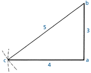
18.5B To Find a Right Angle
Draw a line ab 3x long. At point a scribe an arc 4x long.
At point b scribe an arc 5x long to intersect a c.
Join ac and b, ac and ab are at 900.
18.6A Velocity
| Unit | m/s | kms/h | mile/h |
| mile / hour m/s km/h | 0.44704 1 0.277778 | 1.60934 3.6 1 | 1 2.23694 0.62137 |
The following speeds are approximate and are assumed to be constant and in a straight direction and therefore are also the velocity.
Description marked R are speed records.
18.6B Velocity Comparison
| m/s | km/h | mile/hour | Beaufort Scale | ||
|---|---|---|---|---|---|
| Calm | 0 | <1 | 0 | Smoke rises vertically | |
| Light Air | 0.8 | 3 | 2 | 1 | Smoke rises on angle |
| Man walking | 1.5 | 5.5. | 3.5 | ||
| Light breeze | 2.5 | 9 | 5.6 | 2 | Feel wind on face |
| Gentle breeze | 4.5 | 16 | 10 | 3 | Flags extend |
| Moderate breeze | 7 | 25 | 15.5 | 4 | Raises dust |
| Fresh breeze | 10 | 35 | 22 | 5 | Trees sway, waves |
| Runner 100m R | 10 | 35 | 22 | ||
| Strong breeze | 12.5 | 45 | 28 | 6 | Telegraph wires whistle |
| Racehorse trotting R | 15 | 54 | 33 | ||
| Moderate gale | 15.5 | 56 | 35 | 7 | Difficult to walk |
| Fresh gale | 18.5 | 67 | 42 | 8 | Branches break |
| Racehorse R | 19 | 68 | 42.5 | ||
| Ostrich | 20 | 72 | 45 | ||
| Racing cyclist R | 22 | 79 | 49 | ||
| Strong gale | 23 | 82 | 51 | 9 | Slight building damage |
| Whole gale | 26.5 | 96 | 60 | 10 | Trees uprooted |
| N.Z. Road speed limit | 28 | 100 | 62.5 | ||
| Skier downhill | 28 | 100 | 62.5 | ||
| Storm | 31 | 111 | 69 | 11 | Widespread damage |
| Low wind speed NZS 3604 | 32 | 115 | 71 | ||
| Hurricane | 33.5 | 120 | 75 | 12 | Severe damage |
| Medium wind speed NZS 3604 | 37 | 133 | 83 | ||
| High wind speed NZS 3604 | 44 | 158 | 98 | ||
| AS/NZS 1170 | 45 | 162 | 101 | ||
| Swift - fastest bird | 47 | 169 | 105 | ||
| Very high wind speed NZS 3604 | 50 | 180 | 111 | ||
| AS/NZS 1170 (Cook Strait) | 51 | 184 | 114 | ||
| Moderate cyclone | 55 | 198 | 153 | ||
| Tennis serve R | 66 | 238 | 148 | ||
| Bullet train (Japan) | 69 | 248 | 154 | ||
| Severe tropical cyclone | 70 | 252 | 157 | ||
| TGV express train | 77 | 277 | 172 | ||
| Wind R | 103 | 371 | 230 | ||
| Boeing 747 | 256 | 920 | 572 | ||
| Sound in air | 333 | 1199 | 743 | ||
| Land speed R | 341 | 1228 | 763 | ||
| Rotation of earth at equator | 465 | 1674 | 1040 | ||
| Concorde | 649 | 2336 | 1452 | ||
| 303 Bullet | 792 | 2851 | 1772 | ||
| Lockheed Blackbird R | 981 | 3529 | 2193 | ||
| Moon round the earth | 1000 | 3600 | 2237 | ||
| Sound through steel | 5100 | 18360 | 11408 | ||
| To escape earth’s gravity | 7823 | 28163 | 17500 | ||
| Fastest man has travelled | 11176 | 40234 | 25000 | ||
| Earth round the sun | 29700 | 106920 | 66437 | ||
| Pioneer space probe | 66720 | 240192 | 149248 | ||
| Light and electric waves | 299388000 | 1077614064 | 669600000 | 186,000 miles/sec | |
When cricket and diverter penetration flashings are used, the pitch of the cricket valley will always be less than the pitch of the roof.
To find the pitch of a roof or valley, a simple method is to use a 1m long level measuring stick and measure the rise as shown in drawing 18.7A Measuring Stick Method. The relationship between the rise and the horizontal distance is known as the tangent of the angle and is calculated by using tan f = O/A (being the opposite side divided by the adjacent side). See 18.2 Pitch & Rise Calculator.
250/1000 = 0.25 = 14° (1 in 4)
N.B. Angles A and B are equal.
It is possible to obtain the length of the hypotenuse by using √ a2 + b2
Cricket flashings as described in section 6 can be made to suit any penetration width, any cricket flashing depth to width ratio and roof pitch down to 3°. For simplicity, three angles have been selected.
f X = 45°
f Y = 27°
f Z = 18°
Penetration Width = 2A
Depth = D
Valley = V
D = A
V = √2 = 1.42
D = 1/2A
V = √1.25 = 1.118
D = 1/3A
V = √1.11 = 1.054
To find the cricket valley pitch when the roof pitch is known, it is necessary to find the depth (D) of the cricket. If the depth of the cricket is half of the width of the penetration, as shown for 'Cricket X' the angles are at 45° and there is a defined relationship between the length of the valley of the cricket and the width of the penetration and also between the pitch of the valley of the cricket and the pitch of the roof.
This is 1 : √ 2 = 1.42, which means that to maintain the desired 3° fall in the cricket valley, the minimum roof pitch (4°) can be calculated using table 15.8.
If the depth of the cricket is a quarter or a sixth of the width of the penetration, there are also defined relationships between the pitch of the valley of the cricket and the pitch of the roof.
These are described in table 18.7C Relationships between the pitch of the valley of the cricket and the pitch of the roof as 'Cricket Y' and 'Cricket Z'.
All figures comply with the minimum fall of 1.5°, but all the bold figures will provide a 3° cricket valley pitch. This methodology is valid for all sizes of penetration. However, there is a point at which, having a design with a wide penetration and a low pitch, it becomes uneconomic to pursue the ideal 3° fall in the cricket valley. When the roof pitch is known, the minimum allowable fall of the cricket valley pitch (1.5°) can then be read from table 15.8.
It is permissible to lower the valley pitch because 1.5° allows sufficient fall to clear debris from the valley and therefore qualifies as a warrantable flashing.
A diverter flashing without a cricket design only shifts the position of the cricket to the top over-flashing of the penetration as shown on drawing 9.7.6B Cricket Flashings, unless the penetration is rotated 45° as shown on drawing 9.7.6C Diverter Flashings.
18.7C Relationships between the pitch of the valley of the cricket and the pitch of the roof
| ROOF PITCH | 3° | 4° | 5° | 6° | 7° | 8° | 9° | 10° |
| TANGENT | .0524 | .0699 | .0875 | .1051 | .1228 | .1405 | .1584 | 1763 |
| CRICKET X | 2° | 3° | 3.5° | 4.5° | 10° | |||
| CRICKET Y | 1.5° | 1.75° | 2.25° | 2.75° | 3.25° | 8° | 9° | 10° |
| CRICKET Z | n/a | n/a | 1.5° | 2° | 2.25° | 2.5° | 3° | 3.5° |
Example:
A net penetration width is 550 mm wide and gross width to the flat of the pans is 620 mm (2A).
The back curb is required to have a fall of 3°.
The roof pitch is 7°.
From Table 18.7C Relationships between the pitch of the valley of the cricket and the pitch of the roof . select the cricket - Type Y
Given:
Depth of the Y cricket from drawing 15.8.B (D=1/2A)
Height of the side curb
Height to the top of the cricket
H - Hc = Hr
From Drawing 15.8.C
Find the length of V, S and R.
Right angle triangle, therefore, the length of V.
D = 155mm
H = 130mm
Hc = 70mm
Hr = 60mm
V = √ A2 + D2
A = 346 mm
Right angle triangle, therefore, the length of S.
R = 170 mm
S = √ A² + Hc²
R = 318 mm
2.
3.
4.
5.
6.
7.
8.
9.
10.
11.
12.
From L draw a dotted line at right angles L - M length equal to D
Draw the line K - M (length equal to V)
With centre M scribe an arc length equal to R
With centre K scribe an arc length equal to S
From their point of intersection, N draw a line to K and also to M
With centre K scribe an arc length equal to H.
With centre N scribe an arc length equal to Hr.
Draw a line as a tangent to the two arcs
From point K, draw a line at right angles to intersect this line at O.
From O measure length A to a point P
The shape K-M-N-P-O is the net cricket pattern
Basic knowledge of geometrical drawing and mensuration is required and this section explains the methods which are employed to ensure accurate results.
A straight line. A straight line is a line drawn in the shortest manner between two given points, so any other line between these points is a curved line.
18.8A Parallel Lines

18.8B Perpendicular Line

To draw a perpendicular line. Given a straight line EF, set a compass to any distance more than half the distance EF and, with E and F as centres, describe arcs of radius EG and FH.
A line drawn through the points of intersection of these arcs is perpendicular to EF and bisects the distance EF.
18.8C Dividing a line into equal parts

Connect L and K with a line, and parallel to this draw other lines through points on JL. These divide JK into the required number of equal parts.
18.8D Bisecting and Arc
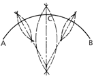
Given an arc AB, set a compass to a distance a little more than half that between the ends and with A and B as centres, describe arcs of equal radii.
A line drawn through the points of intersection will bisect AB. This method can be employed to divide the arc into any number of even parts by repetition. Further, the method may be used to find the centre of any given arc by further bisecting AC and CB.
Lines taken through the intersecting points of these latter arcs, when produced, will intersect at the centre of the arc AB.
18.8E Bisecting an Angle

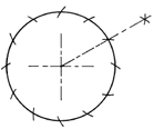
18.8F Dividing a Circle into Six Equal Parts
18.8G Developing the Frustrum of a True Cone
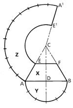
Draw the elevation X with base diameter AB, the vertical height CD to the desired cone angle and add the section line EF to the elevation. With centre D and radius DA describe a semicircle Y on the base, and divide the circumference of this into six equal parts.
To draw the development Z: With centre C and radius CB, describe an arc AA¹ whose length equals the circumference of cone base.
This may be obtained by marking off along the arc from A spaces equal to parts in the semicircle Y but double in number.(12)
With C as centre and radius CE, draw the arc EE1 and add the line CA¹.
The figure AA1E1E is the development Z of the frustrum.
To do this, drop a perpendicular from F to F¹ and extend the base line AB.
An offset diagram is now made by measuring distances B¹F¹, B¹G, and B¹H, setting these off from F¹ on base line AB and drawing lines to F.
The lengths FF¹, FG, and FH, etc., are now true lengths.
To draw the development Z:
Draw a centre line C¹O. At right angles to C¹ draw A²B² equal to AB.
From C1, set off distance C1F1, equal to FB.
Join A² and B² to F¹. With centre A² and radius F¹G, draw a short arc to be cut by an arc of F¹G radius struck from F1 to obtain point G1.
Similarly, with A² as centre and radius FH, draw an arc, to be cut by an arc of GH radius struck from point G¹, thus obtaining point H¹.
Draw a line through, A² and H¹ and produce same to intersect the centre line C¹O at O.
Repeat the process with. B² as centre for long radii, thus completing one quarter of the whole development.
To complete the pattern, draw a curve through points H¹G¹F¹ and repeat in the other sections of the development.
18.8H Developing a Square Base to a Circular Top
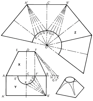
Draw the elevation X, making the base AB, vertical height CD, and diameter of top EF.
Draw a half plan Y on the base, drawing the semicircle E1F1 and dividing one half of this into a number of equal parts, F¹G, GH, HJ, and JK.
Through points F¹, G, H, J, and K, draw lines to B¹.
Before proceeding to the development it is necessary to find the true lengths of B¹K, B¹J, B¹H, B¹G, and B¹F¹.


