Access the Code of Practice online

This registration will be required once-only per browser/device, which is achieved using a cookie stored on your device.

There is no password required, and your information will not be shared with any third parties.

Please register and accept the terms for the NZMRM online COP
By ticking this box you confirm that you have read and accept the Terms listed below


Disclaimer

Although the information contained in this Code has been obtained from sources believed to be reliable, New Zealand Metal Roofing Manufacturers Inc. makes no warranties or representations of any kind (express or implied) regarding the accuracy, adequacy, currency or completeness of the information, or that it is suitable for the intended use.

Compliance with this Code does not guarantee immunity from breach of any statutory requirements, the New Zealand Building Code or relevant Standards. The final responsibility for the correct design and specification rests with the designer and for its satisfactory execution with the contractor.

While most data have been compiled from case histories, trade experience and testing, small changes in the environment can produce marked differences in performance. The decision to use a particular material, and in what manner, is made at your own risk. The use of a particular material and method may, therefore, need to be modified to its intended end use and environment.

New Zealand Metal Roofing Manufacturers Inc., its directors, officers or employees shall not be responsible for any direct, indirect or special loss or damage arising from, as a consequence of, use of or reliance upon any information contained in this Code.

New Zealand Metal Roofing Manufacturers Inc. expressly disclaims any liability which is based on or arises out of the information or any errors, omissions or misstatements.

If reprinted, reproduced or used in any form, the New Zealand Metal Roofing Manufacturers Inc. (NZMRM) should be acknowledged as the source of information.

You should always refer to the current online Code of Practicefor the most recent updates on information contained in this Code.

Scope

This Code of Practice provides requirements, information and guidelines, to the Building Consent Authorities, the Building Certifier, Specifier, Designer, Licensed Building Practitioner, Trade Trainee, Installer and the end user on the design, installation, performance, and transportation of all metal roof and wall cladding used in New Zealand.

The calculations and the details contained in this Code of Practice provide a means of complying with the performance provisions of the NZBC and the requirements of the Health and Safety at Work Act 2015.

The scope of this document includes all buildings covered by NZS 3604, AS/NZS 1170 and those designed and built under specific engineering design.

It has been written and compiled from proven performance and cites a standard of acceptable practice agreed between manufacturers and roofing contractors.

The drawings and requirements contained in this Code illustrate acceptable trade practice, but recommended or better trade practice is also quoted as being a preferred alternative.

Because the environment and wind categories vary throughout New Zealand, acceptable trade practice must be altered accordingly; in severe environments and high wind design load categories, the requirements of the NZBC will only be met by using specific detailing as described in this Code.

The purpose of this Code of Practice is to present both Acceptable Trade Practice and Recommended Trade Practice, in a user-friendly format to ensure that the roof and wall cladding, flashings, drainage accessories, and fastenings will:

  • comply with the requirements of B1, B2, E1 E2 and E3 of the NZBC;
  • comply with the design loading requirements of AS/NZS 1170 and NZS 3604 and with AS/NZS 1562;
  • have and optimised lifespan; and
  • be weathertight.

COP v24.12:Internal-Moisture; Underlay

10.11 Underlay 

Condensation that forms on the cold under-surface of the roof system must be contained until ambient conditions allow it to evaporate. Containment is normally achieved by using an absorbent roofing underlay. It is the role of roofing underlay to absorb moisture temporarily and then release it back into the atmosphere.

A common misconception holds that the roofing underlay acts as a drainage plane, channelling condensation from underside of the metal roof to the gutter. In practice, most of the condensation forms on the underside of the underlay. Although roofing underlays are permeable, they still form a substantial vapour check; and as they are in contact with the roof, they are at a similar temperature. Any condensation that does form on the underside of the roof and falls onto the underlay generally only tracks down the underlay as far as the next purlin, where it is trapped and is absorbed by the underlay. Underlay is also affected by holes from roofing fasteners so is unreliable as a “second roof”.

As it is designed to execute its primary purpose of aiding in the management of internal moisture, underlay should not be used as a compensation for unreliable weatherproofing design and installation


10.11B Condensation Under Roofing Underlay

Most condensation on the underside of the roof system occurs under the roofing underlay.

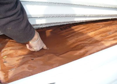
The presence of pooling condensate on the upper side of a roofing underlay indicates that the absorptive capacity of the underlay has been exceeded. Not only the underlay will be saturated, but also the ceiling structural members and insulation; mould, corrosion, and decay are inevitable. The cure is to decrease the amount of moisture entering the ceiling cavity or increase ventilation of the ceiling space.

10.11C Chronic Condensation 

Chronic condensation problem caused by induction of moist air into the ceiling cavity. Although the underlay here is doing a good job of containing the surface water, the timber trusses, insulation, and ceiling below the underlay were  saturated with water.

Underlay also acts as a partial air barrier. (Rigid air barriers are also available.) Water will generally only go where gravity or air pressure takes it. By effectively reducing the space behind cladding, the underlay allows rapid pressure equalisation on each side of the cladding, thereby reducing the ability of water to enter the space.

10.11.1 Underlay Standards 

Permeable underlays must comply with NZS 2295, Amendment 1:2017, as shown in Properties of Roofing Underlay, or have an appropriate product certification such as a Codemark certificate.

Reflective foil underlays must comply with AS/NZS 4200.1:2017

10.11.1A Minimum Requirements for Underlays for Metal Roof Cladding

Classification R1R3R2R4
Grade HeavyweightHeavyweightSelf-supportSelf-support
Type KraftSyntheticKraftSynthetic
Application  Residential or light commercial buildings  
PropertyUnit    
Absorbencyg/m²≥ 150≥ 150≥ 150≥ 150
Water Vapour ResistanceMN s/g≤ 7≤ 0.5≤ 7≤ 0.5
Water resistancemm head≥ 100≥ 100≥ 100≥ 100
Tensile Strength MDKN/m≥ 9≥ 3≥ 11≥ 3
Tensile Strength CDKN/m≥ 4.5≥ 2≥ 6≥ 2.5
Edge Tear Resistance MDN≥ 40≥ 100≥ 70≥ 150
Edge Tear Resistance CDN≥ 35≥ 80≥ 55 ≥ 130
 

Based on Table B1 of NZS 2295 Amendment 1:2017.

  • Self-supporting (S/S) is defined as strong enough to support its own weight up to a 1200 mm span.
  • pH between 5.5 and 80.
  • Kraft based underlays shall have shrinkage less than 0.5% and maximum run-length of 10 m.
  • Synthetic underlays may have any run length.
  • Any underlay is regarded as fire-retardant if it has a Flammability Index (FI) of 5 or less when tested to AS/NZS 1530 Part 2.


10.11.2 Underlay Requirements 

The NZBC requires underlays under profiled metal roofing and direct-fixed metal wall cladding on lined residential buildings to be both permeable and absorbent. 

Underlays fixed to the dry side of a lined drained cavity may be permeable and non-absorbent. 

Underlays are not required in unlined structures, but in such cases non-permeable, non-absorbent underlays such as foil are typically used to increase reflectivity and to minimise condensation.

In some wall and roof applications, the underlay is required to be Fire Retardant with Flammability Index ≤5 when tested to AS1530.2. Refer NZBC C/AS3-AS6, clause 4.17.8 

Underlays designated as self-supporting can be laid without support at spans up to 1.2 m.

Other requirements for underlays vary for different cladding systems, but the important features of absorbency, permeability, water resistance, tensile strength, edge tear resistance, PH, and durability are important to comply with the requirements of the NZBC.

The Code of Practice recommends synthetic self-supporting fire-retardant underlays for residential roofing applications.

10.11.3 Types Of Underlay 

Apart from their fire retardance and ability to self-support, underlays are classified according to their absorbency and permeability.

Permeable and Absorbent:

  • Kraft paper-based — bitumen impregnated paper
  • Synthetic — 2 or 3 layers, using permeable synthetic film strengthened by sandwiched non-woven fabric.

Permeable, non-absorbent:

  • Synthetic permeable non-absorbent underlays are mainly used as wall wrap inside a drained cavity or with direct fixed absorbent claddings.

Non-Permeable, non-absorbent:

  • foil — Reflective aluminium foil over a flexible substrate. These can be either double-sided or white-faced.

10.11.4 Underlay Usage 

In lined buildings and dwellings, an absorbent permeable underlay is required under metal roofs. The same applies to direct-fixed steel wall cladding, but underlays used behind a drained cavity are not required to be absorbent.

For aesthetic reasons, a foil-faced (or white-faced) vapour check layer may be used in unlined commercial or industrial applications to reduce heat radiation from the roof cladding and provide enhancement of light. For insulated applications, foil is normally used as a vapour check under the insulation and an absorbent permeable underlay used above with a 20 mm gap from the roof cladding.

On non-residential dwellings, profiled roof-light sheeting running in continuous lengths from the ridge can have multiple skins to avoid condensation dripping from the sheeting or plastic sheet with a spacer can be used to lessen condensation. Roof underlays should not be laid continuously under translucent roof or wall cladding.

10.11.5 Underlay Durability 

NZBC Clause B2.3.1 requires building elements that are non-structural and are moderately difficult to replace to have a durability of 15 years. It also requires building elements that are part of a building system and are difficult to replace to have the same durability or to be designed so materials with lesser durability can be replaced without removal of more durable elements.

Compliance with NZBC B2, therefore, requires roofing underlay to have durability equal to that of the roof cladding and no less than 15 years.

For durability reasons, the roof underlay should ideally finish on to an eaves flashing, so that the underlay is not exposed to UV in the long run or be able to flap or vibrate in the wind.

10.11.6 Installing Underlay 

Underlay can be laid vertically or horizontally. Side laps must be a minimum of 150 for roofs and 75 mm for walls; end laps must be a minimum of 150 mm for both roof and wall cladding. At the eaves, the underlay should terminate on the upper side of the eaves flashing or overhang fascia by no more than 20 mm.

The COP recommends that all underlay is terminated at the ridge, and if not it should be slit or slotted to allow passive ventilation of the ceiling cavity.

The COP allows roof and wall underlay to be laid either vertically or horizontally in all cases. However, that is in divergence with E2/AS1, so it is advised for buildings within the scope of E2/AS1 (ie, buildings designed within the scope of NZS 3604) that the requirements of the local TA is sought before diverging from E2/AS1.

Rips smaller than 75 mm on walls or roofs can be repaired using a compatible flashing tape, but roof underlay damage greater than this requires a new piece of underlay captured by the cladding fastenings.

Flue penetrations must have a minimum distance of 50 mm from the outer liner to any underlay or flammable material.

E2/AS1 requires self-support underlay laid horizontally on support to be used at pitches below 10°. That is not a requirement of the COP as underlay support is no substitute for good ventilation design and effective weathertight details.

When using vented battens, the underlay should be positioned on the upper side of the batten, directly under the roof cladding. Having the underlay directly under the roof allows the battens to vent the roof cavity directly and allows the underlay to perform its normal design function; putting roofing underlay under ventilated battens impedes roof cavity ventilation

With re-roofs in any material, it is not acceptable to lay a new roof over existing underlay or underlay support, unless the latter is in “as new” condition. See  14.20 Fixing Aluminium Sheeting.

Wall underlays must have a minimum side lap of 150 mm, and an end lap of 75 mm. Wall underlay on a drained cavity should be on the dry (inside) face of the cavity, and be rigid enough to restrain wall insulation from contacting the cladding, or have secondary strapping to achieve such.

10.11.6.1 Horizontal Laying 

Horizontally laid underlay must be supported if used under long-run metal roofing, unless both edges are supported by purlins. Under metal tiles, self-supporting underlay can be laid over the roof trusses at spans up to 1.2 m.

Underlay laid horizontally must be laid starting at the lowest point of the roof, running over the bottom purlin and must overlap into the gutter by a maximum of 20 mm to prevent wicking. When an eaves flashing is used the underlay should terminate on the downslope of the flashing.

To lay roof underlay horizontally, more than one roll can be progressively unrolled, one roofing sheet width at a time. Running multiple rolls straight can, however, be difficult in windy conditions.

10.11.6.2 Vertical Laying 

The laps on vertically laid roof underlay may face in either direction, as the direction of lay is usually dictated by construction sequencing or wind direction at the time of laying.

The bottom end of vertically laid roof underlay must overlap into the gutter by a maximum of 20 mm to prevent wicking. When an eaves flashing is used the underlay should terminate on the downslope of the flashing.

10.11.6.3 Underlay Support 

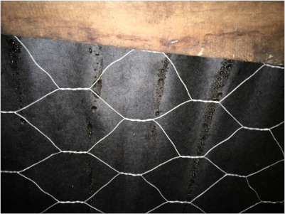
Self-supporting underlays in lined roof spaces may be laid unsupported at spans up to 1.2 m. Other underlays must be supported. Underlay support may be safety mesh, hexagonal galvanised wire netting, builders’ tape, or other suitably strong and durable material.

Safety mesh must be designed and installed to comply with the requirements of the AS/NZS 4389:2015

Corroded galvanised safety mesh and wire netting can be damaging to any metal roofing and especially to pre-painted aluminium. Pre-painted aluminium cladding must be protected from contact with potentially corroding steel including netting, staples, or fasteners, See 14.20 Fixing Aluminium Sheeting