Basic knowledge of geometrical drawing and mensuration is required and this section explains the methods which are employed to ensure accurate results.
A straight line. A straight line is a line drawn in the shortest manner between two given points, so any other line between these points is a curved line.
18.8A Parallel Lines

18.8B Perpendicular Line

To draw a perpendicular line. Given a straight line EF, set a compass to any distance more than half the distance EF and, with E and F as centres, describe arcs of radius EG and FH.
A line drawn through the points of intersection of these arcs is perpendicular to EF and bisects the distance EF.
18.8C Dividing a line into equal parts

Connect L and K with a line, and parallel to this draw other lines through points on JL. These divide JK into the required number of equal parts.
18.8D Bisecting and Arc

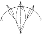
Given an arc AB, set a compass to a distance a little more than half that between the ends and with A and B as centres, describe arcs of equal radii.
A line drawn through the points of intersection will bisect AB. This method can be employed to divide the arc into any number of even parts by repetition. Further, the method may be used to find the centre of any given arc by further bisecting AC and CB.
Lines taken through the intersecting points of these latter arcs, when produced, will intersect at the centre of the arc AB.
18.8E Bisecting an Angle

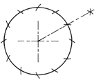
18.8F Dividing a Circle into Six Equal Parts

18.8G Developing the Frustrum of a True Cone

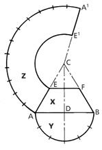
Draw the elevation X with base diameter AB, the vertical height CD to the desired cone angle and add the section line EF to the elevation. With centre D and radius DA describe a semicircle Y on the base, and divide the circumference of this into six equal parts.
To draw the development Z: With centre C and radius CB, describe an arc AA¹ whose length equals the circumference of cone base.
This may be obtained by marking off along the arc from A spaces equal to parts in the semicircle Y but double in number.(12)
With C as centre and radius CE, draw the arc EE1 and add the line CA¹.
The figure AA1E1E is the development Z of the frustrum.
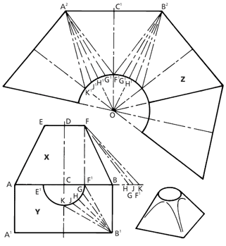
To do this, drop a perpendicular from F to F¹ and extend the base line AB.
An offset diagram is now made by measuring distances B¹F¹, B¹G, and B¹H, setting these off from F¹ on base line AB and drawing lines to F.
The lengths FF¹, FG, and FH, etc., are now true lengths.
To draw the development Z:
Draw a centre line C¹O. At right angles to C¹ draw A²B² equal to AB.
From C1, set off distance C1F1, equal to FB.
Join A² and B² to F¹. With centre A² and radius F¹G, draw a short arc to be cut by an arc of F¹G radius struck from F1 to obtain point G1.
Similarly, with A² as centre and radius FH, draw an arc, to be cut by an arc of GH radius struck from point G¹, thus obtaining point H¹.
Draw a line through, A² and H¹ and produce same to intersect the centre line C¹O at O.
Repeat the process with. B² as centre for long radii, thus completing one quarter of the whole development.
To complete the pattern, draw a curve through points H¹G¹F¹ and repeat in the other sections of the development.
18.8H Developing a Square Base to a Circular Top

Draw the elevation X, making the base AB, vertical height CD, and diameter of top EF.
Draw a half plan Y on the base, drawing the semicircle E1F1 and dividing one half of this into a number of equal parts, F¹G, GH, HJ, and JK.
Through points F¹, G, H, J, and K, draw lines to B¹.
Before proceeding to the development it is necessary to find the true lengths of B¹K, B¹J, B¹H, B¹G, and B¹F¹.
