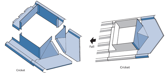
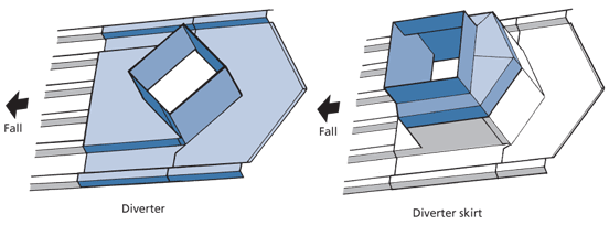
Nomenclature
Roof underlay should lap the back curb by a minimum of 50 mm.
- have back and side curbs 50 mm higher than the cladding profile;
- have side and back curbs with a minimum height of 100 mm—except where the penetration is wider than 600 mm or the catchment area exceeds 20 m², when the height must be increased by the height of the profile rib;
- not restrict maximum likely water flow;
- be at least as durable as the roof cladding;
- not rely solely on sealant for the prevention of water ingress;
- have enough fall to avoid ponding and debris build-up;
- have a back-curb minimum lap of 150 mm under the cladding unless it is sealed;
- have a minimum 100 mm clearance between the end of the sheeting upside of the penetration and the back-curb upstand;
- have no fasteners that penetrate the back curb; and
- have primary fastening to the structure.
Where a penetration is used on a trapezoidal ribbed roof, the ribs upside of the penetration should be closed by folding, cutting, and fastening, or with end caps or plastic closed cell filler strips formed to match the profile.
The ends of the ribs should be closed, but not sealed, to allow ventilation and to disperse any condensation draining into this space. Building underlay should overlay the flashing to drain condensation, because water ingress at the penetration caused by condensation is often attributed to a leaking flashing.
The end of the sheets on the downside of the penetration should be stopended vertically to the full height of the rib using a pull-up stop-end. If the position is exposed or in a high wind area, the ribs should be cut and the pans dog-eared or foam closures used. See Stopends.
In an exposed or high wind area, it is necessary to provide a further wind barrier by using closed cell filler blocks to reduce the pressure differential in this cavity.
The design of a penetration flashing must not rely on sealant alone and must ensure that the lap is sufficient to shed water naturally.
The over-flashing skirt or apron should overlap the curb by a minimum of 50 mm and have a stiffened edge; it is not normally fixed to the side-curb. If the site exposure or the size of the skirt necessitates fixing to the side curb, the fixings should provide for expansion and for the vibration that occurs on penetrations for venting fans or other dynamic equipment.
All side curb flashings should be made from one piece, having an upstand the same height as the back-curb, and a side-lap that overlaps the sheets.
The side-curb can be cranked or splayed to preserve the penetration hole size, or the skirt can be cranked or splayed to match the profile module. See Splayed Skirt.
- Log in to post comments


